An experiment with waves
 المؤلف:
Richard Feynman, Robert Leighton and Matthew Sands
 المصدر:
The Feynman Lectures on Physics
 الجزء والصفحة:
Volume I, Chapter 37
 2024-04-17
 1513
1513

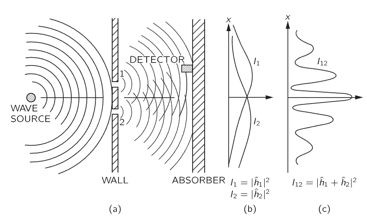
Fig. 37–2. Interference experiment with water waves.
Now we wish to consider an experiment with water waves. The apparatus is shown diagrammatically in Fig. 37–2. We have a shallow trough of water. A small object labeled the “wave source” is jiggled up and down by a motor and makes circular waves. To the right of the source, we have again a wall with two holes, and beyond that is a second wall, which, to keep things simple, is an “absorber,” so that there is no reflection of the waves that arrive there. This can be done by building a gradual sand “beach.” In front of the beach we place a detector which can be moved back and forth in the x-direction, as before. The detector is now a device which measures the “intensity” of the wave motion. You can imagine a gadget which measures the height of the wave motion, but whose scale is calibrated in proportion to the square of the actual height, so that the reading is proportional to the intensity of the wave. Our detector reads, then, in proportion to the energy being carried by the wave—or rather, the rate at which energy is carried to the detector.
With our wave apparatus, the first thing to notice is that the intensity can have any size. If the source just moves a very small amount, then there is just a little bit of wave motion at the detector. When there is more motion at the source, there is more intensity at the detector. The intensity of the wave can have any value at all. We would not say that there was any “lumpiness” in the wave intensity.
Now let us measure the wave intensity for various values of x (keeping the wave source operating always in the same way). We get the interesting-looking curve marked I12 in part (c) of the figure.
We have already worked out how such patterns can come about when we studied the interference of electric waves. In this case we would observe that the original wave is diffracted at the holes, and new circular waves spread out from each hole. If we cover one hole at a time and measure the intensity distribution at the absorber, we find the rather simple intensity curves shown in part (b) of the figure. I1 is the intensity of the wave from hole 1 (which we find by measuring when hole 2 is blocked off) and I2 is the intensity of the wave from hole 2 (seen when hole 1 is blocked).
The intensity I12 observed when both holes are open is certainly not the sum of I1 and I2. We say that there is “interference” of the two waves. At some places (where the curve I12 has its maxima) the waves are “in phase” and the wave peaks add together to give a large amplitude and, therefore, a large intensity. We say that the two waves are “interfering constructively” at such places. There will be such constructive interference wherever the distance from the detector to one hole is a whole number of wavelengths larger (or shorter) than the distance from the detector to the other hole.
At those places where the two waves arrive at the detector with a phase difference of π (where they are “out of phase”) the resulting wave motion at the detector will be the difference of the two amplitudes. The waves “interfere destructively,” and we get a low value for the wave intensity. We expect such low values wherever the distance between hole 1 and the detector is different from the distance between hole 2 and the detector by an odd number of half-wavelengths. The low values of I12 in Fig. 37–2 correspond to the places where the two waves interfere destructively.
You will remember that the quantitative relationship between I1, I2, and I12 can be expressed in the following way: The instantaneous height of the water wave at the detector for the wave from hole 1 can be written as (the real part of)  where the “amplitude”
  is, in general, a complex number. The intensity is proportional to the mean squared height or, when we use the complex numbers, to
  . Similarly, for hole 2 the height is
  and the intensity is proportional to
  When both holes are open, the wave heights add to give the height
  and the intensity
  Omitting the constant of proportionality for our present purposes, the proper relations for interfering waves are

You will notice that the result is quite different from that obtained with bullets (Eq. 37.1). If we expand  we see that

where δ is the phase difference between  and
and  . In terms of the intensities, we could write

The last term in (37.4) is the “interference term.” So much for water waves. The intensity can have any value, and it shows interference.
 الاكثر قراءة في ميكانيكا الكم
 اخر الاخبار
اخبار العتبة العباسية المقدسة


