
تاريخ الرياضيات

الاعداد و نظريتها

تاريخ التحليل

تار يخ الجبر

الهندسة و التبلوجي


الرياضيات في الحضارات المختلفة

العربية

اليونانية

البابلية

الصينية

المايا

المصرية

الهندية


الرياضيات المتقطعة

المنطق

اسس الرياضيات

فلسفة الرياضيات

مواضيع عامة في المنطق


الجبر

الجبر الخطي

الجبر المجرد

الجبر البولياني

مواضيع عامة في الجبر

الضبابية

نظرية المجموعات

نظرية الزمر

نظرية الحلقات والحقول

نظرية الاعداد

نظرية الفئات

حساب المتجهات

المتتاليات-المتسلسلات

المصفوفات و نظريتها

المثلثات


الهندسة

الهندسة المستوية

الهندسة غير المستوية

مواضيع عامة في الهندسة

التفاضل و التكامل


المعادلات التفاضلية و التكاملية

معادلات تفاضلية

معادلات تكاملية

مواضيع عامة في المعادلات


التحليل

التحليل العددي

التحليل العقدي

التحليل الدالي

مواضيع عامة في التحليل

التحليل الحقيقي

التبلوجيا

نظرية الالعاب

الاحتمالات و الاحصاء

نظرية التحكم

بحوث العمليات

نظرية الكم

الشفرات

الرياضيات التطبيقية

نظريات ومبرهنات


علماء الرياضيات

500AD

500-1499

1000to1499

1500to1599

1600to1649

1650to1699

1700to1749

1750to1779

1780to1799

1800to1819

1820to1829

1830to1839

1840to1849

1850to1859

1860to1864

1865to1869

1870to1874

1875to1879

1880to1884

1885to1889

1890to1894

1895to1899

1900to1904

1905to1909

1910to1914

1915to1919

1920to1924

1925to1929

1930to1939

1940to the present

علماء الرياضيات

الرياضيات في العلوم الاخرى

بحوث و اطاريح جامعية

هل تعلم

طرائق التدريس

الرياضيات العامة

نظرية البيان
RELAY CIRCUITS AND CONTROL PROBLEMS-Design of sequential relay circuits from given conditions
المؤلف:
J. ELDON WHITESITT
المصدر:
BOOLEAN ALGEBRA AND ITS APPLICATIONS
الجزء والصفحة:
124-134
4-1-2017
2229
In the preceding section, two examples of sequential circuits were given in which the lengths of the various time intervals depended on the operate or release time of the relays involved. Such circuits can be designed to operate with reasonably specific time intervals. Through a variety of methods, such as the use of conducting sleeves around the magnetic core or the incorporation of dashpots, the operate or release time of a relay can be varied from less than five milliseconds up to an interval of several seconds. Thermal relays provide time delays up to thirty seconds. We could cite many special problems related to the construction and use of such relays, but this would take us rather far afield from Boolean algebra, the central topic of this book. Consequently, we will concentrate on the design of sequential circuits in which the sequential nature of the circuit is determined by the input conditions. For the most part, we will consider the problem of designing circuits to provide specified outputs from a set of completely specified sequential input conditions. Such input signals can originate in a variety of ways-from the dialing of a telephone, from brushes that pick up signals from contacts on a rotating shaft, from the output of a sequential circuit in another part of the device being designed, etc. We will not be concerned here with the source of input information, but with the design of a required sequential output from given input conditions.
In a combinational circuit, each occurrence of a specified set of input conditions produces the same output. In a sequential circuit, this is not always the case. We will construct circuits for which the sequence of inputs (rather than the combination of input conditions that might hold at a given time) is the determining factor. It will be necessary to construct circuits capable of remembering past sets of conditions as well as of interpreting existing conditions. To provide the needed memory feature will require, in addition to relays controlled by input conditions, the introduction of new relays to be controlled in part by hold paths.
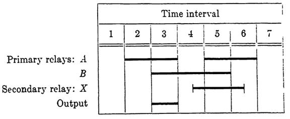
In a sequential circuit, any relay controlled by an input path will be termed a primary relay. Relays introduced in addition to primary relays, and controlled through contacts on the primary relays, will be termed secondary relays. Consider the sequence diagram of Fig. 1-1, which represents both the sequential operation of two primary relays and a desired output. The output, which is to be a signal provided by a closed path, is to occur in interval 3 only. Note that a combinational circuit will not suffice since the same input combination occurs in both intervals 3 and 5. This means that a secondary relay will have to be introduced to differentiate between these intervals. Figure 1-2 shows a suitable choice of intervals in which the secondary relay X may operate to provide this service. Note that the

FIG. 1-1. Sequence of primary relay operations and desired output.

FIG. 1-2. Sequence diagram of Fig. 1-1 with secondary relay.

FIG. 1-3. Circuit for the diagram of Fig. 1-2.

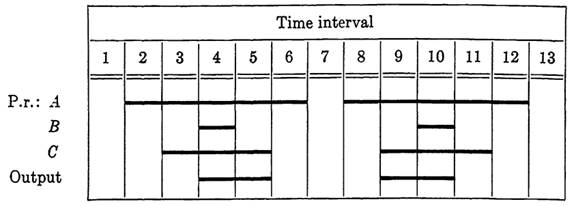
FIG. 1-4. A sequence diagram.
diagram shows X operated during part of interval 4, all of 5, and part of 6. We are assuming that the control path of X can be determined so that the conditions of interval 4 will serve to operate X and those of interval 6 will serve to release X. The time lag shown is caused by the operate and release times for X. That is, the operate path of X will be closed during the entire interval 4, but a short time elapses before the contacts on X close. Assuming, for the moment, that the control path for X has been designed, the function representing the output path is clearly g = abx', since A and B are operated and X is released only in interval 3.
The control path for X can be designed in two parts, as discussed earlier. The operate path should close in interval 4, but not sooner. Hence a suitable operate function is f0 = a'b. Since the condition closing the operate path is not present in interval 5, when it is desired to maintain the operation of X, a hold path is also needed. The hold function is given by fh = b. The control function is therefore F = a'b + bx. The corresponding circuit is shown in Fig. 1-3, where the output consists of a closed lead to ground for the appropriate conditions. The output could also be obtained as a completely separate 2-terminal circuit if desired.
As a second illustration, suppose that the action of primary relays and the output of a circuit are to be as shown in Fig. 1-4. To determine the secondary relays needed for the desired output, note that it will be necessary to distinguish interval 5 from 7, interval 3 from 11, and intervals 2 and 4 from 8 and 12. A single secondary relay operating first in interval 6 and releasing in 13 would serve this purpose. However, if the relay is to release in 13, it will also release in 9 unless an additional relay is provided to distinguish between intervals 9 and 13. To avoid this, we have indicated in Fig. 1-5 a relay X operating twice during the time of the chart, and releasing in both intervals 9 and 13. Based on the conditions of intervals 6 and 10, the operate function for X could be written as f0 =abc + ab'c'. However, the combination A and B operated, C released never occurs, so the term abc' will not affect the circuit; and abc' + abc =ab, which allows us to simplify f0 to ab + ab'c'. Similarly, ab'c' + abc' = ac', and the final form for the operate function may be taken as f0 = ab + ac'. We call a combination such as this, which does not occur at any time in the sequence chart, an invalid combination. Any such combination may be used to simplify control functions whenever desired.
In designing the hold path for X, it is well to remember that although the hold path must be closed during any interval in which X is to operate, other than those in which the control circuit maintains the operation of X, it does no harm if parts of the hold circuit are closed during certain other intervals as well. In particular, since the hold path always passes through a make contact x on X, no harm is done if the path is closed (except at x) during any interval in which X is released. The only important require-

FIG. 1-5. The diagram of FIG. 1-4 with secondary relay added.

FIG. 1-6. Circuit for the diagram of Fig. 1-5.
ment on the hold path is that it must open during each interval in which X is to release.
According to the specifications given in Fig. 1-5, X is to release just after each release of C, and C is operated in each interval during which the hold path must be closed. Hence a simple hold function is fh = c. Combining the operate and hold functions, we obtain the control function for XasF= a(b+c')+cx.
The output path is now just a combinational circuit closed under the conditions represented in intervals 5, 6, 8, 11, and 12. Five conditions are involved (even though intervals 8 and 12 are alike) because the operation of X changes during interval 6. The output function is therefore given by g = bcx' + abc + b'cx. The circuit showing both the control of X and the output path is given in Fig. 1-6. The output is the 2-terminal circuit joining T1 to T2.
As these examples show, the first steps in designing a circuit to meet the output requirements on a sequential diagram are to decide how many secondary relays will be needed and to determine a suitable operating sequence for these relays. Once this has been done, the control paths of

FIG. 1-7. A sequence diagram with two identical primary cycles.

FIG. 1-8. Diagram of Fig. 1-7, with secondary relays added.
secondary relays can be designed with the help of Boolean functions, or in simple cases, by inspection. The output path is then simply a combinational circuit.
As a third example, consider the sequence chart of Fig. 1-7, in which a particular sequence of inputs occurs twice and the output is different in the two cases. To write a suitable output function, it will be necessary to distinguish between the first and second sequences of operation and to distinguish between intervals 3 and 5 in the first sequence, and again between 9 and 11 in the second.
In attempting to determine the number of secondary relays needed, there is no formal approach which will give an immediate answer. We can say in general that n relays can distinguish between at most 2" identical combinations of inputs. However, the problem of possible control for these secondary relays may complicate the situation and require one or more additional relays for control purposes only.
In Fig. 1-8, one choice of operating sequence is shown for three secondary relays, which are sufficient for this diagram.
TABLE 1-1
OUTPUT CONDITIONS FOR THE DIAGRAM OF FIG. 1-6

First, relay X is added to distinguish between intervals 3 and 5 and between intervals 9 and 11.
The control of this relay will be a simple matter since it is to operate when B is operated, and to release when A releases. The control function may be written as
Fx= b + ax.
Next, relay Y is added to distinguish the first cycle of A, B, and C from the second. However, with this operating sequence for Y, the control of Y cannot be managed from A, B, C, and X alone, since the relay would operate again in interval 8. To distinguish interval 2 from 8, a third relay Z is introduced. The operate condition for Y is A operated, B, C, and Z released. Y must then hold until all three are released. A suitable control function is Fy= ac'z'x' + ay. The operate condition for Z is A, C, X, and Y operated, B released, and Z is to hold until B is operated.
The control function may be written as Fz = ab'cxy + b'z. The race condition between the release of X and Y in interval 7 does not affect Z since Z will hold for as long as B is released.
Table 1-1 represents the output conditions. 'Note that the output is dependent on A, B, C, X, and Y only. Z is used only in controlling Y. The dashes in row 1 indicate that the states of X and Y are not needed to determine output in intervals 4 and 8, since these are the only two intervals in which A, B, and C are all operated. The output function is g = b + c(xy + x'y'). The circuit for this diagram is not shown, but can be readily drawn from these functions. There are other sequences for secondary relays which might work equally well, or better.
In summary, the procedure for the design of a sequential circuit from a given sequence chart is first to determine, by trial and error, the number of secondary relays needed. In connection with this, the secondary relays must be introduced in such a sequence as to make distinctions between like combinations of inputs which affect the desired outputs. Finally, the control circuits for secondary relays and the output circuits are designed. Much of this is of necessity done by inspection of the sequence chart. The choice of operating sequence for secondary relays is determined in part from conditions which lead to simple control circuits. Boolean algebra

FIGURE 1-9
is convenient for writing the control and output functions, but unfortunately, the algebra alone is not sufficiently versatile to represent the entire problem. As we have seen, Boolean functions correspond only to those parts of the design which are combinational in nature. Sequential operation is handled primarily by the ingenuity of the designer. This section was included, not primarily as an application of the algebra, but as an extension of earlier sections to show the limitations of Boolean algebra in design problems and to illustrate the versatility of relay circuits.
 الاكثر قراءة في الجبر البولياني
 اخر الاخبار
اخبار العتبة العباسية المقدسة

الآخبار الصحية


 قسم الشؤون الفكرية يصدر كتاباً يوثق تاريخ السدانة في العتبة العباسية المقدسة
 "المهمة".. إصدار قصصي يوثّق القصص الفائزة في مسابقة فتوى الدفاع المقدسة للقصة القصيرة
 (نوافذ).. إصدار أدبي يوثق القصص الفائزة في مسابقة الإمام العسكري (عليه السلام)


