

 الفيزياء الكلاسيكية
 الكهربائية والمغناطيسية
 علم البصريات
 الفيزياء الحديثة
 النظرية النسبية
 الفيزياء النووية
 فيزياء الحالة الصلبة
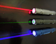
 الليزر
 علم الفلك
 المجموعة الشمسية
 الطاقة البديلة
 الفيزياء والعلوم الأخرى
 مواضيع عامة في الفيزياء
|
Read More
Date: 15-4-2021
Date: 1-4-2021
Date: 9-4-2021
|
Amplitude limiting
The forward breakover voltage of a germanium diode is about 0.3 V; for a silicon diode it is about 0.6 V. In the last chapter, you learned that a diode will not conduct until the forward bias voltage is at least as great as the forward breakover voltage. The “flip side” is that the diode will always conduct when the forward bias exceeds the breakover value. In this case, the voltage across the diode will be constant: 0.3 V for germanium and 0.6 V for silicon.
This property can be used to advantage when it is necessary to limit the amplitude of a signal, as shown in Fig. 1. By connecting two identical diodes back-to-back in parallel with the signal path (A), the maximum peak amplitude is limited, or clipped, to the forward breakover voltage of the diodes. The input and output waveforms of a clipped signal are illustrated at B. This scheme is sometimes used in radio receivers to prevent “blasting” when a strong signal comes in.
The downside of the diode limiter circuit is that it introduces distortion when limiting is taking place. This might not be a problem for reception of Morse code, or for signals that rarely reach the limiting voltage. But for voice signals with amplitude peaks that rise well past the limiting voltage, it can seriously degrade the audio quality, perhaps even rendering the words indecipherable.

Fig. 1: At A, two diodes can work as a limiter. At B, the peaks are cut off by the action of the diodes.


|
|
|
|
التوتر والسرطان.. علماء يحذرون من "صلة خطيرة"
|
|
|
|
|
|
|
مرآة السيارة: مدى دقة عكسها للصورة الصحيحة
|
|
|
|
|
|
|
نحو شراكة وطنية متكاملة.. الأمين العام للعتبة الحسينية يبحث مع وكيل وزارة الخارجية آفاق التعاون المؤسسي
|
|
|